- #Raspberry pi minicom how to
- #Raspberry pi minicom install
- #Raspberry pi minicom Pc
- #Raspberry pi minicom download
#Raspberry pi minicom download
To do so we can download the latest firmware from the getting started guide (pico_micropython_20210121.uf2 at the time of the review), then press the BOOTSEL key on the board while connecting to a computer with a USB port, and release the key after connection. We should first copy MicroPython firmware to the board. The hardware setup is now complete, and all I need is a Micro USB to USB-A cable to connect the board to my laptop. The GPIO markings on Raspberry Pi Pico are only shown on the bottom of the board, so when the board is connected to a breadboard a pinout diagram helps. It would be a shame not to use those headers so I inserted Raspberry Pi Pico into a breadboard and added an LED with the accompanying circuitry.ĥV is connected to VBUS (pin 40), GND to pin 38, and I decide to use the GPIO the closest to the LED namely GP15 (pin 20). Changing the motion sensitivity or sleep timeout can easily fix this issue, and I could complete the task at hand. I did not move the soldering enough so it failed to detect any activity and entered into sleep. The soldering iron worked great for about one minute, and then I started to have problems with soldering… Looking a the screen I could see Zzzz and the temperature dropped. In theory, we could just get started with the board alone, but since I got some headers with my board, I also took the opportunity to try out Pine64 Pinecil soldering iron powered by MINIX NEO P2 USB-C power supply. The instructions will be similar for Windows and Mac OS. I went to the official documentation to get started, but I had to look around to achieve what I wanted to do, namely blinking some LEDs, so I’ll document my experience with my own getting started guide for Raspberry Pi Pico using a computer running Ubuntu 20.04 operating system. So, the next step is to disable the console.Raspberry Pi Pico board was just launched last Thursday, but thanks to Cytron I received a sample a few hours after the announcement, and I’ve now had time to play with the board using MicroPython and C programming language.

However, Raspberry Pi’s UART is used by console by default as you saw in the output on step 3-4.
#Raspberry pi minicom Pc
Now, UART connection between Raspberry Pi and PC is established. Add the lines below at the end of the file. Select “Append CR-LF” in “Transmitted Text”.ģ-1. Select Port number you checked on step 2-2.Ģ-6. Launch Termite and click on “Settings” button.Ģ-4. Open “Device Manager” and check the COM port number USB-Serial cable is using.

#Raspberry pi minicom install
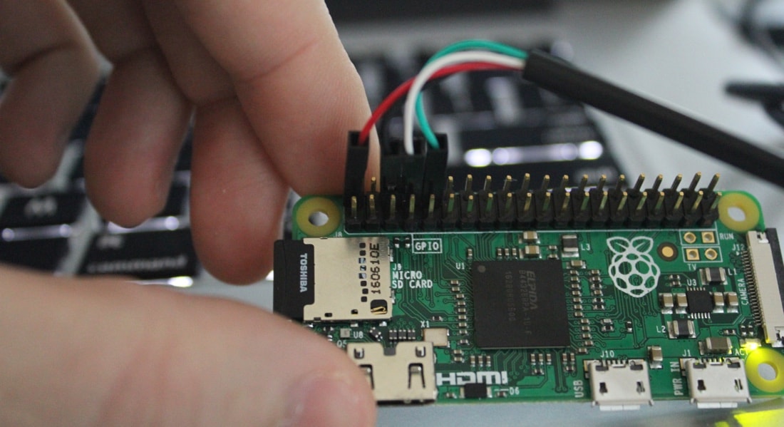
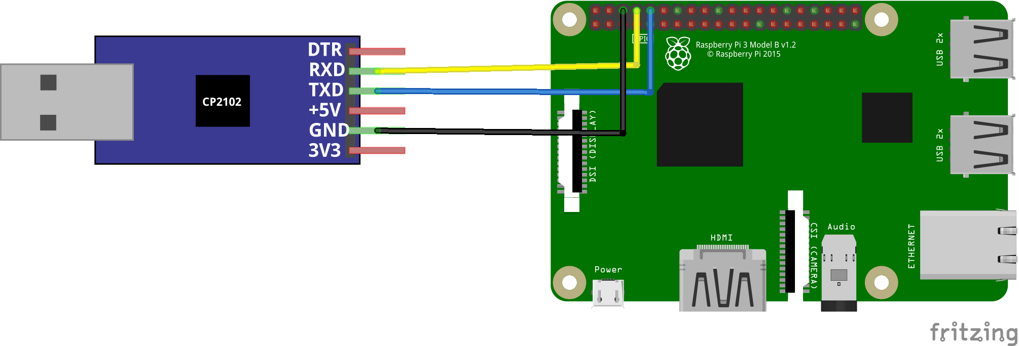
To send and receive serial data, let’s install and setup a terminal emulator program on PC.Ģ-2. Setting up terminal emulator on Windows PC Connect USB-Serial cable to USB port on PCĢ. Connect the other side of jumper wires to Raspberry Pi’s GPIO pins. Connect jumper wires to USB-Serial cable for Tx, Rx, and GND.ġ-2.


#Raspberry pi minicom how to
This post shows how to setup serial communication between Raspberry Pi and PC using a USB-Serial cable.


 0 kommentar(er)
